Loss budget
Give the operating point and the data of the switch, the diode and the inductor or transformer core, all in SI units. The loss budget simulates the converter at ten loads and nine switching frequencies. At each point it adjusts the duty ratio until the output is at its set value, then applies the catalogue’s loss equations to the simulated currents. It shows:
- the losses at full load, each with the equations behind it;
- the losses as stacked bars against the load and against the switching frequency, with the efficiency.
The link under the table opens the full-load point in the simulator, non-ideal parts included.
How it computes the losses
Section titled “How it computes the losses”At each point the load resistance follows from the output voltage and the power. The duty ratio starts at the value of the ideal converter, in CCM or in DCM depending on against (K). A search then adjusts it until the simulated output is within one part in a thousand of its set value: secant steps, kept between the tries that gave an output below and above the set value, and halving that interval when a step would leave it. If no duty ratio reaches the set value, the tool keeps the closest try and says so. The forward converter’s duty ratio stops at its reset limit. The losses of the simulated period are then sorted into buckets:
- Conduction. Resistive loss of the rms switch current in and of the rms inductor current in the winding resistance [Erickson & Maksimović 2020, Ch. 3].
- Capacitive switching. The switch discharges the node capacitance at every turn-on (capacitive turn-on loss), from the simulated switch voltage just before turn-on, which includes any DCM ringing.
- Gate drive. The gate-charge loss, which the driver and the gate resistances dissipate, not the switch channel.
- Core. The flux density follows the inductor current, so half the current swing gives the ac flux amplitude (flux density from the current). The Steinmetz equation gives the loss per unit volume, and the core volume the total. The tool also shows the peak flux density at the peak current, from the same equation, to be checked against the core’s saturation flux density; it does not check it itself.
- Diode. The diode loss from the simulated average and rms diode current.
- Leakage energy (flyback). The energy stored in the leakage inductance at the peak primary current (leakage energy) is lost once per period (leakage power). A dissipative clamp also absorbs energy from the reflected voltage, so this is a lower bound for its loss.
, , and the node capacitance are also in the simulated circuit, so the currents include their effect. The diode’s slope resistance, the gate drive, the core and the leakage inductance are not: their losses are computed from the simulated currents. The output power is the power the load takes over the simulated period, the ripple included, and the efficiency is the output power over the output power plus all the buckets.
Limitations
Section titled “Limitations”- No overlap loss. The simulated transitions are instantaneous, so the loss while a hard-switched transistor’s voltage and current overlap during a transition is not included [Erickson & Maksimović 2020, Ch. 4].
- Core loss is an estimate. The Steinmetz coefficients describe sinusoidal excitation [Erickson & Maksimović 2020, Ch. 10], and the converter’s winding voltage is rectangular.
- One winding resistance, one core. is in series with the inductance in every interval. For the flyback it is the winding resistance referred to the primary: the primary’s while the switch is on, the secondary’s divided by while the diode conducts, one value for both [Erickson & Maksimović 2020, Ch. 6]. The core data belong to the inductor, or to the flyback’s transformer; the forward converter’s transformer core and windings are not included.
- No thermal model. The resistances do not rise with temperature.
Screenshot
Section titled “Screenshot”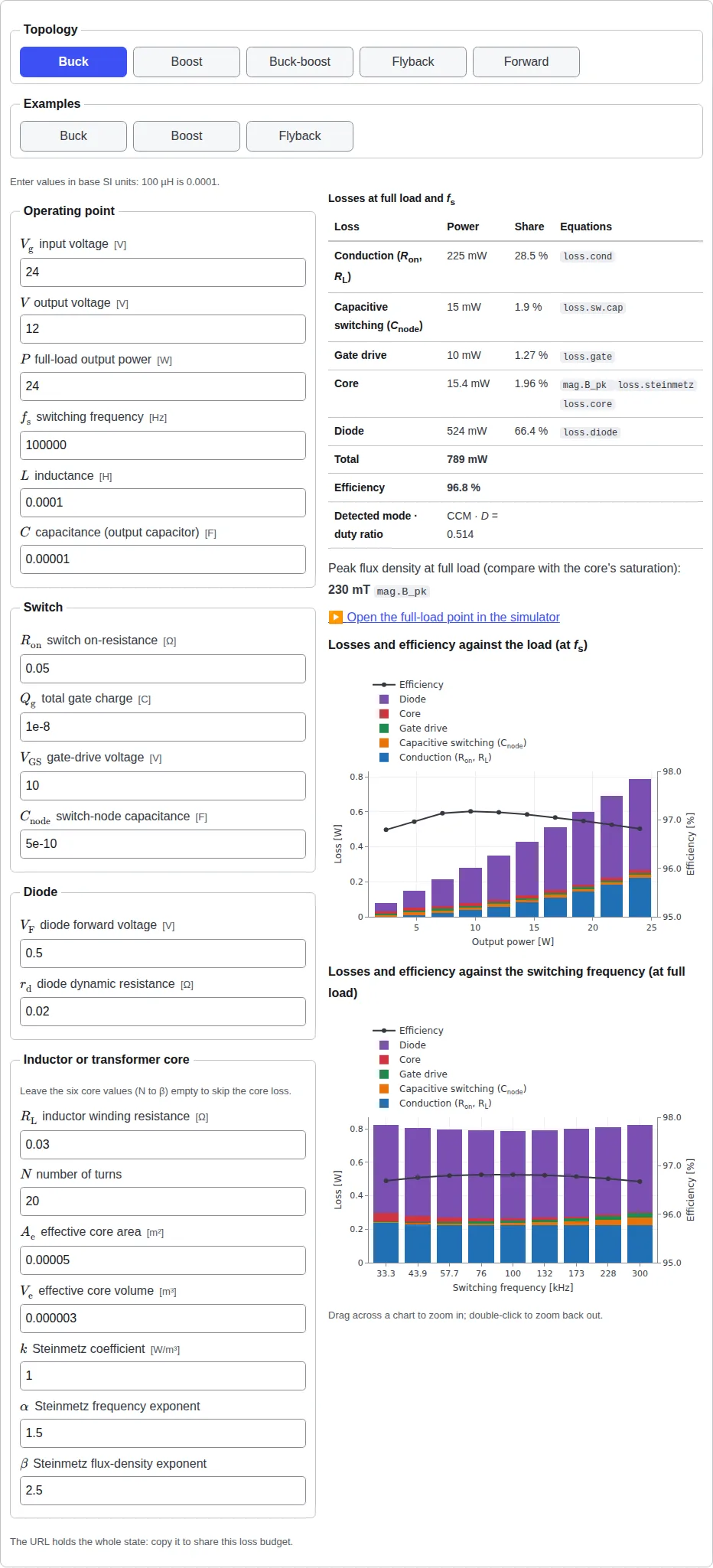
The numbers in the examples, presets and exercises on this site are synthetic: round teaching values, not data from any real design.