Source matcher
A linear source is an open-circuit voltage behind a source resistance , and it delivers the most power into a matched load [Alexander & Sadiku 2017, Sec. 4.8]. A flyback in DCM with a fixed duty ratio draws power from its input like a resistor, so it can be matched to such a source [Erickson & Maksimović 2020, Ch. 15]. The source matcher takes the source, the flyback and its fixed output, all in SI units. It shows:
- the operating point: the bus voltage, the power drawn, and its share of the available power;
- that share against the source amplitude, where CCM takes over;
- the switch voltage that a larger power needs;
- optionally, the flyback simulated cycle by cycle over a varying source amplitude.
Each result names its equation. The link under the table opens the operating point in the simulator.
What it computes
Section titled “What it computes”The available power
Section titled “The available power”A linear source delivers its most power into a load equal to its own resistance (maximum power from a linear source).
The flyback as a resistor
Section titled “The flyback as a resistor”In DCM with a fixed duty ratio, the flyback’s average input current is proportional to its input voltage: its input is a resistance, the loss-free resistor, which passes the power on instead of dissipating it [Singer 1990] [Erickson & Maksimović 2020, Ch. 15]. With a linear source, this resistance and the source resistance divide the source voltage (bus voltage of a loss-free resistor).
The flyback takes the same share of the available power at any source amplitude, the whole of it when its resistance matches the source’s [Alexander & Sadiku 2017, Sec. 4.8] (extraction by a loss-free resistor).
Where CCM takes over
Section titled “Where CCM takes over”The flyback stays in DCM while its input is below the critical input voltage. A source strong enough to raise the divider voltage above it drives the flyback into CCM, and CCM holds the bus at the critical voltage. The flyback then acts as a constant-voltage sink, whose share of the available power depends on the source amplitude [Alexander & Sadiku 2017, Sec. 4.8] (constant-voltage extraction).
The tool finds the source amplitude at which this starts by solving the divider equation for . The extraction chart shows both regimes. While the flyback is a resistor, the share is flat. Once CCM holds the bus, the share is the constant-voltage sink’s, which is 1 where the source amplitude is twice the critical voltage and falls beyond. If is larger than , the bus reaches the critical voltage below that amplitude, and the share first rises to 1.
More power needs a higher switch voltage, up to the critical voltage
Section titled “More power needs a higher switch voltage, up to the critical voltage”Through the same input resistance, a larger power needs a higher bus voltage (input voltage for a given power).
The switch blocks the bus voltage plus the reflected output voltage (switch voltage). That holds up to the critical voltage: there CCM holds the bus, and the switch voltage stays at its CCM value whatever power the source then pushes in. The largest power the flyback draws as a resistor is therefore the power a DCM converter draws at the critical voltage. If the switch’s rating lies below the CCM value, the rating caps it earlier, where the switch voltage reaches the rating; the tool says which limit applies. The switch chart plots the switch voltage against the power: the resistor’s rising branch, then the CCM plateau.
A varying source amplitude
Section titled “A varying source amplitude”With an envelope, the source amplitude follows a rectified sine or points you enter, as a fraction of . The tool then simulates the flyback cycle by cycle with the simulator’s source-driven model, each switching cycle at the source amplitude of its start, so an envelope period must span at least twenty switching cycles.
The run starts from an empty bus, seven slowest time constants of the bus before an envelope period. While the flyback is a resistor, that time constant is at most ; once CCM holds the bus, the averaged bus and magnetizing inductance form a second-order system [Erickson & Maksimović 2020, Ch. 7], whose slower mode can take much longer, with a stiff source above all. The tool then repeats the envelope period until it repeats itself, and shows the last one. Its bus voltage and power are averaged over each switching cycle.
The power drawn is the power the source delivers into the bus at the bus voltage [Alexander & Sadiku 2017, Sec. 4.8] (power into a constant-voltage sink).
It is negative while the bus feeds the source back, when the source amplitude falls below the bus voltage. Its sum over the period, divided by the available energy, gives the share over the envelope. The number of switching cycles in a run is limited, to keep it within a few seconds; the tool says so when an envelope would need more.
Worked example
Section titled “Worked example”| Symbol | Value | How it is obtained |
|---|---|---|
| source open-circuit voltage | 150 V | given |
| source resistance | 10 kΩ | given |
| magnetizing inductance (primary) | 20 mH | given |
| switching frequency | 10 kHz | given |
| duty ratio | 0.2 | given |
| output voltage | 5 V | given |
| output-diode forward drop | 500 mV | given |
| turns ratio, secondary/primary | 0.1 | given |
| switch voltage rating | 400 V | given |
| input bus capacitor | 10 µF | given |
| emulated input resistance | 10 kΩ | Input resistance of a DCM buck-boost or flyback (loss-free resistor) |
| input voltage | 75 V | Bus voltage of a loss-free resistor fed by a linear source |
| share of the available power extracted | 1 | Extraction fraction of a loss-free resistor |
| largest power available | 563 mW | Maximum power from a linear source |
| input voltage at the CCM/DCM boundary | 220 V | Flyback: input voltage at the CCM/DCM boundary (fixed D, fixed output) |
| switch voltage while off | 130 V | Flyback switch voltage while off (without the leakage spike) |
Operating mode: DCM: the flyback is a loss-free resistor (: holds)
Here the flyback’s resistance equals the source resistance, so it takes all of the available power, 563 mW, at a bus voltage of 75 V. That is well below the critical input voltage, 220 V, so the flyback stays in DCM, and its switch blocks 130 V. Raise in the tool until the bus reaches the critical voltage: the flyback becomes a constant-voltage sink, and its share of the available power falls. The simulator’s worked example is this flyback at a higher source amplitude, in that regime.
The “Rectified-sine envelope” example runs the same flyback over an envelope whose peaks reach the constant-voltage regime. The bus follows the source while the flyback is a resistor, and stays at the critical voltage near the peaks.
Limitations
Section titled “Limitations”- Linear source. The source is a constant voltage behind a constant resistance. A source whose resistance changes with its operating point is outside this model.
- Ideal flyback. Apart from the output diode’s drop, the flyback is loss-free: the envelope simulation has no on-resistance, winding resistance or node capacitance. The output is a fixed voltage (a battery, for example). The switch voltage leaves out the spike from the leakage inductance at turn-off; the clamp check sizes the clamp for it.
- Averaged bus. The operating point and the charts use averages: they assume the bus capacitor holds the bus nearly constant over a switching period. With a small capacitor the bus ripples, and the tool says so; the simulator link shows the difference.
- Slow envelope. Each switching cycle sees a constant source amplitude, so the envelope must change little within one switching period.
Screenshot
Section titled “Screenshot”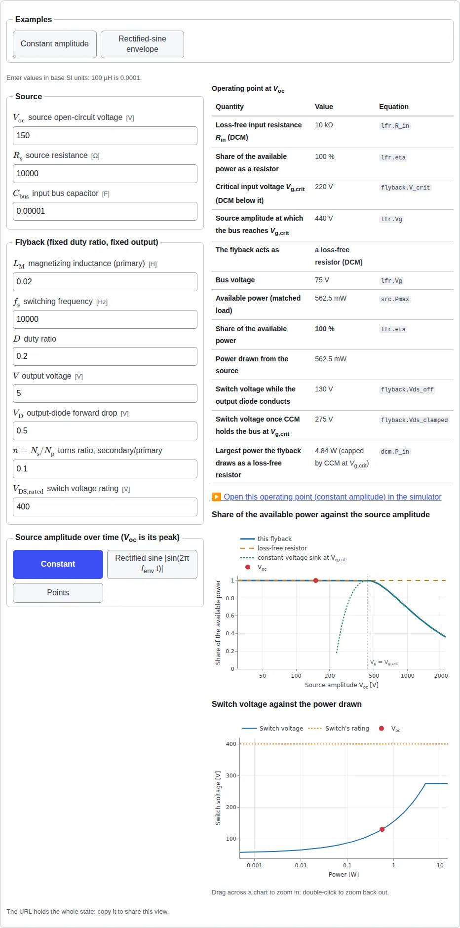
The numbers in the examples, presets and exercises on this site are synthetic: round teaching values, not data from any real design.